Posts

How to Use Timer-1 in AT89C1051 (13-bit Mode)

Image
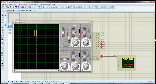
The following code demonstrate, how to generate clock of 100Hz using timer-1 in 13-bit mode. Every 5000 micro-second timer-1 overflow flag goes high and  port P3.0 is inverted. The code is written in Keil uVision2 IDE and simulation is done with Proteus 8.0. At the end of code, you can find complete project files for download. Code Using Keil uVision2 #include #include // proto-types void ConfigTimer1(void); void MonitorTimer1OverflowFlag(void); void Delayms(unsigned int x_time); // pin labling sbit PULSE = P3^0; sbit LED = P1^0; void main(void) { // make pins as output PULSE = 0; LED = 0; // config timer-1 ConfigTimer1(); while(1) { PULSE = ~PULSE; MonitorTimer1OverflowFlag(); } } void ConfigTimer1(void) { // master clock is 12MHz // timer clock is 1/12th => 1MHz // in 13-bit mode timer overflow // after 8,191 usec. // for overflow every 5,000 usec // 8,191-5,000 = 3,191 (0x0C77) TL1 = 0x77; TH1 = 0x0C; // set timer-1 mode-0 (13-bit)...
How to Use Timer-1 in AT89C1051 (16-bit Mode)

Image
The following code demonstrate, how to generate clock of 1.0Hz using timer-1 in 16-bit mode. Every 50,000 micro-second timer-1 overflow flag goes high and  port P3.0 is inverted. The code is written in Keil uVision2 IDE and simulation is done with Proteus 8.0. At the end of code, you can find complete project files for download. Code Using Keil uVision2 #include #include // proto-types void ConfigTimer1(void); void MonitorTimer1OverflowFlag(void); void Delayms(unsigned int x_time); // pin labling sbit PULSE = P3^0; sbit LED = P1^0; void main(void) { // make pins as output PULSE = 0; LED = 0; // config timer-1 ConfigTimer1(); while(1) { PULSE = ~PULSE; MonitorTimer1OverflowFlag(); } } void ConfigTimer1(void) { // master clock is 12MHz // timer clock is 1/12th => 1MHz // in 16-bit mode timer overflow // after 65536 usec. // for overflow every 50,000 usec // 65,536-50,000 = 15,536 (0x3CB0) TL1 = 0xB0; TH1 = 0x3C; // set timer-1 mode-1 (16-bit) TMOD = 0x10; // start ti...

How to Use Timer-0 in AT89C1051 (Split Mode)

Image
The following code demonstrate, how to use timer-0 in split mode. In this mode TL0 and TH0 both are incremented by 1 on each clock cycle. Both timer-0 registers are incremented independently. Timer flag TF0 is generate when TL0 count reaches 256 and TF1 is generated when TH0 count reaches 256. The code is written in Keil uVision2 IDE and simulation is done with Proteus 8.0. At the end of code, you can find complete project files for download. Code Using Keil uVision2 #include <REG51.H> #include <stdio.h> // proto-types void ConfigTimerSplitMode(void); void MonitorTimer1OverflowFlag(void); void Delayms(unsigned int x_time); // pin labling sbit CLK0 = P1^0; sbit CLK1 = P1^1; sbit TF0_STATUS = P3^0; sbit TF1_STATUS = P3^1; void main(void) { // make as output CLK0 = 0; CLK1 = 0; TF0_STATUS = 0; TF1_STATUS = 0; // config timer in split mode ConfigTimerSplitMode(); while(1) { // flag status TF0_STATUS = TF0; if(TF0 == 1) { CLK0 = ~CLK0; TF0 = 0; TL0 = 0; } TF1_STATUS = T...

How to Blink LED with PIC16F877A

Image
The following code demonstrate, how to write a program to blink LED. LED is connected to PORTB bit-1.  The code is written in “mikroC PRO for PIC v.5.6.1” IDE and simulation is done with Proteus 8.0 SP0. At the end of code, you can find complete project files for download. Code in mikroC // direction signal sbit LED_dir at TRISB.B1; // bit labels portb sbit LED at PORTB.B1; void main(void) { // set direction as output LED_dir = 0; // init LED LED = 0; while(1) { LED = 0; Delay_ms(500); LED = 1; Delay_ms(500); } } Download Files For download “mikroC PRO for PIC” project and “Proteus 8.0” simulation files,  click here .

How to Program All Ports as Output of PIC16F877A

Image
The following code demonstrate, how to write a program to use all ports of PIC16F877A as outputs. Bit level programming technique is used. As PORTA is multi-purpose port, to set PORTA as digital you have to write 0x06 value to ADCON1 register and PORTA.4 is open drain bit so it is externally pull-up by 4.7k resistor. The code is written in “mikroC PRO for PIC v.5.6.1” IDE and simulation is done with Proteus 8.0 SP0. At the end of code, you can find complete project files for download. Code in mikroC // functions proto-types void PortABitValue(int val); void PortBBitValue(int val); void PortCBitValue(int val); void PortDBitValue(int val); void PortEBitValue(int val); void PortAInitAsDO(void); void PortBInitAsDO(void); void PortCInitAsDO(void); void PortDInitAsDO(void); void PortEInitAsDO(void); // direction signals porta sbit LED_A0_dir at TRISA.B0; sbit LED_A1_dir at TRISA.B1; sbit LED_A2_dir at TRISA.B2; sbit LED_A3_dir at TRISA.B3; sbit LED_A4_dir at TRISA.B4; sbit LED_A5_dir ...

How to Program Switch and LED Connected with PIC16F877A

Image
The following code demonstrate, how to write a program that scan the switch status and turn on and off LED. The switch is connected at PORTE bit-0 and LED connected on PORTB bit-0. When switch is read as high state, the LED is turn-on and when switch state is low, LED is turn-off. The switch debouncing rate is 5msec. The code is written in “mikroC PRO for PIC v.5.6.1” IDE and simulation is done with Proteus 8.0 SP0. At the end of code, you can find complete project files for download. Code in mikroC // switch connected on porte #define SW_AT_PORT PORTE // debounce rate 5msec #define DBOUNCE_RATE 5 // direction signal sbit LED_dir at TRISB.B0; sbit SW_dir at TRISE.B0; // bit labels portb sbit LED at PORTB.B0; sbit SW at PORTE.B0; // old state save flag bit oldstate_one_to_zero; bit oldstate_zero_to_one; void main(void) { // set porta and porte as digital ADCON1 = 0x06; // set direction as output LED_dir = 0; // set direction as input SW_dir = 1; // init LED LED = 0; // init old s...

How to Program ADC in PIC16F877A (Internal Voltage Reference)

Image
The following code demonstrate, how to write a program that gets ADC sample from channel-0 (AN0) and 10-bits digital data is displayed on PORTC:PORTB. The internal reference voltage is used that is 5 VDC. The step voltage is 4.88 mv with 0.28125% error (1/1024 * 5v = 4.88mv). The code is written in “mikroC PRO for PIC v.5.6.1” IDE and simulation is done with Proteus 8.0 SP0. At the end of code, you can find complete project files for download. Code in mikroC void main(void) { unsigned adc_value = 0; // set direction as output TRISB = 0x00; TRISC = 0x00; // as input TRISA = 0xFF; // init to zero PORTB = 0x00; PORTC = 0x00; // Initialize ADC module with default settings ADC_Init(); while(1) { // read analog value from ADC module channel 0 adc_value = ADC_Get_Sample(0); PORTB = adc_value; PORTC = (adc_value>>8) & 0x03; } } Download Files For download “mikroC PRO for PIC” project and “Proteus 8.0” simulation files,  click here .