Posts

How to Program Interrupts in PIC16F877A

Image
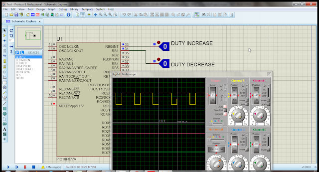
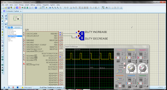
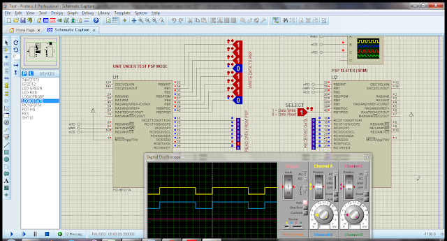
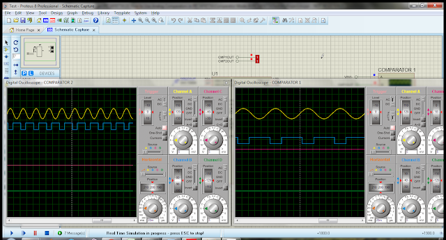
There are 15 interrupts available in PIC16F877A controller. I will try to demonstrate individual interrupt so that you can easily understand. The list is the following. 1. External Interrupt 2. RB Port Change Interrupt 3. Timer 0 Interrupt 4. Timer 1 Interrupt 5. Parallel Slave Port Read/Write Interrupt 6. A/D Converter Interrupt 7. USART Receive Interrupt 8. USART Transmit Interrupt 9. SPI (Slave) Interrupt 9. Synchronous Serial Port Interrupt 10. CCP1 (Capture, Compare, PWM) Interrupt 11. CCP2  (Capture, Compare, PWM) Interrupt 12. TMR2 to PR2 Match Interrupt 13. Comparator Interrupt 14. EEPROM Write Operation Interrupt 15. Bus Collision Interrupt 1. External Interrupt (RB0) The following code demonstrates how to use external interrupt (RB0). A push button is connected to RB0/INT, when push button is pressed a high to low signal is generated. As in option register external interrupt is configured on falling edge so interrupt is generated and interrupt serv

How to Program CCP2 Module in PIC16F877A (10-Bit PWM Mode)

Image
The following code demonstrate how to use CCP2 module in PWM mode with 10-bit of resolution. On initialization PWM duty cycle is set to zero, when "DUTY INCREASE" button is pressed pulse width start increasing and by pressing "DUTY DECREASE" button, pulse width start decreasing. The code is written in “mikroC PRO for PIC v.6.6.3” IDE and simulation is done with Proteus 8.0 SP0. At the end of code, you can find complete project files for download. Code in mikroC // define crystal frequency #define _XTAL_FREQ 20000000 // timer-2 prescalar #define TMR2_PRESCALE 4 sbit DUTY_INC_Dir at TRISB.B0; sbit DUTY_DEC_Dir at TRISB.B1; sbit DUTY_INC at PORTB.B0; sbit DUTY_DEC at PORTB.B1; long pwm_freq = 5000; PWM2_Initialize(void); PWM2_Duty(unsigned int duty); void main(void) { unsigned int count = 0; // make as input DUTY_INC_Dir = 1; DUTY_DEC_Dir = 1; // init pwm2 PWM2_Initialize(); PWM2_Duty(0); while(1) { if(DUTY_INC ==

How to Program CCP1 Module in PIC16F877A (10-Bit PWM Mode)

Image
The following code demonstrate how to use CCP1 module in PWM mode with 10-bit of resolution. On initialization PWM duty cycle is set to zero, when "DUTY INCREASE" button is pressed pulse width start increasing and by pressing "DUTY DECREASE" button, pulse width start decreasing. The code is written in “mikroC PRO for PIC v.6.6.3” IDE and simulation is done with Proteus 8.0 SP0. At the end of code, you can find complete project files for download.   Code in mikroC // define crystal frequency #define _XTAL_FREQ 20000000 // timer-2 prescalar #define TMR2_PRESCALE 4 sbit DUTY_INC_Dir at TRISB.B0; sbit DUTY_DEC_Dir at TRISB.B1; sbit DUTY_INC at PORTB.B0; sbit DUTY_DEC at PORTB.B1; long pwm_freq = 5000; PWM1_Initialize(void); PWM1_Duty(unsigned int duty); void main(void) { unsigned int count = 0; // make as input DUTY_INC_Dir = 1; DUTY_DEC_Dir = 1; // init pwm1 PWM1_Initialize(); PWM1_Duty(0); while(1) { if

How to Program Parallel Slave Port (PSP) in PIC16F877A

Image
The following code demonstrate how to use parallel slave port module. The controller offers a mechanism by which an 8-bit parallel bidirectional data transfer can be achieved between a PIC16F877A and other PSP supporting devices. The PIC16F877A's Port-D and Port-E are used in this data transfer. For this data transfer, Port-D is configured as a parallel slave port (PSP) by setting bit-4 of TRISE Register. The pins of Port-E function as control pins for data transfer. The code is written in “mikroC PRO for PIC v.6.6.3” IDE and simulation is done with Proteus 8.0 SP0. At the end of code, you can find complete project files for download. UUT Code in mikroC // function proto-type void PSP_Setting(void); void main(void) { // portb as input port TRISB = 0xFF; // portc as output port TRISC = 0x00; // portc init to 0x00 PORTC = 0x00; PSP_Setting(); while(1) { // write request to PSP if(TRISE.IBF == 1) { PORTC = PORTD; // auto clear

How to Use Analog Comparators in PIC16F877A (Mode-6)

Image
The following code demonstrate how to use analog comparator module in mode-6. In this mode comparator-1 and comparator-2 positive (+) inputs are connected to the comparator voltage reference module. The external inputs are applied on the negative (-) input of comparators. You can map C1OUT and C2OUT on any general purpose IOs. The code is written in “mikroC PRO for PIC v.6.6.3” IDE and simulation is done with Proteus 8.0 SP0. At the end of code, you can find complete project files for download. Code in mikroC // comparator voltage reference formula // when CVRR = 1 // CVREF = (VR<3:0>/24) x (CVRSRC) // Four Inputs Multiplexed to Two Comparators #define CMP_MODE    6 // user assign comparator o/p signals sbit CMP1_Dir at TRISC.B0; sbit CMP2_Dir at TRISC.B1; sbit CMP1_Out at PORTC.B0; sbit CMP2_Out at PORTC.B1; // function proto-type void CMP_Setting(void); void main(void) { CMP1_Dir = 0; CMP2_Dir = 0; // init value CMP1_Out

How to Use Analog Comparators in PIC16F877A (Mode-1)

Image
The following code demonstrate how to use analog comparator module in mode-1. In this mode comparator-1 can be used and comparator-2 will be off. The default output of the comparator-1 can be monitor on C1OUT on RA4 pin. You can also map this output on general purpose IOs. The code is written in “mikroC PRO for PIC v.6.6.3” IDE and simulation is done with Proteus 8.0 SP0. At the end of code, you can find complete project files for download. Code in mikroC // One Independent Comparator with Output #define CMP_MODE    1 // default comparators o/p signals sbit C1OUT_Dir at TRISA.B4; sbit C1OUT_Out at PORTA.B4; // user assign comparator o/p signals sbit CMP1_Dir at TRISC.B0; sbit CMP1_Out at PORTC.B0; // function proto-type void CMP_Setting(void); void main(void) { // set direction as output C1OUT_Dir = 0; CMP1_Dir = 0; // init value C1OUT_Out = 0; CMP1_Out = 0; CMP_Setting(); while(1) { C1OUT_Out = CMCON.C1OUT; // user assign

How to Use Analog Comparators in PIC16F877A (Mode-5)

Image
The following code demonstrate how to use analog comparator module in mode-5. In this mode positive input of the two comparators are combine. The default output of each comparator can be monitor on C1OUT on RA4 pin and C2OUT on RA5 pin. You can also map theses outputs on general purpose IOs. The code is written in “mikroC PRO for PIC v.6.6.3” IDE and simulation is done with Proteus 8.0 SP0. At the end of code, you can find complete project files for download. Code in mikroC // Two Common Reference Comparators with Outputs #define CMP_MODE    5 // default comparators o/p signals sbit C1OUT_Dir at TRISA.B4; sbit C2OUT_Dir at TRISA.B5; sbit C1OUT_Out at PORTA.B4; sbit C2OUT_Out at PORTA.B5; // user assign comparator o/p signals sbit CMP1_Dir at TRISC.B0; sbit CMP2_Dir at TRISC.B1; sbit CMP1_Out at PORTC.B0; sbit CMP2_Out at PORTC.B1; // function proto-type void CMP_Setting(void); void main(void) { // set direction as output C1OUT_Dir