Posts

Showing posts from May, 2017

How to Blink LED using AT89C1051

Image
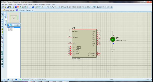
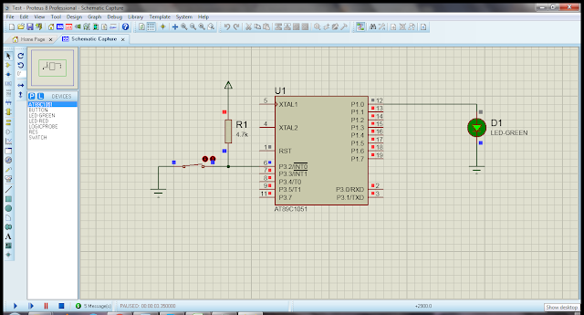
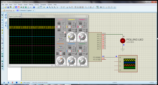
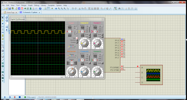
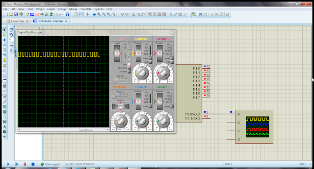
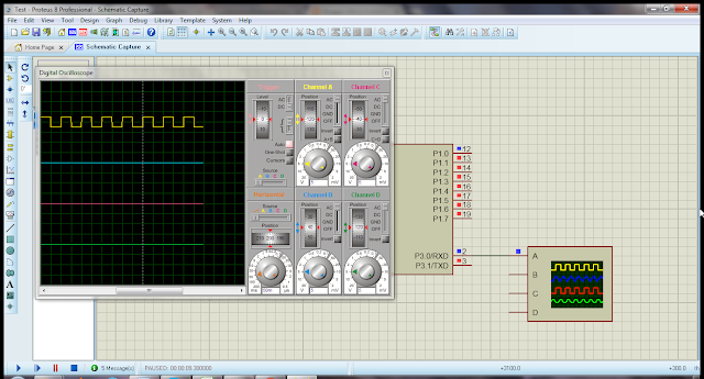
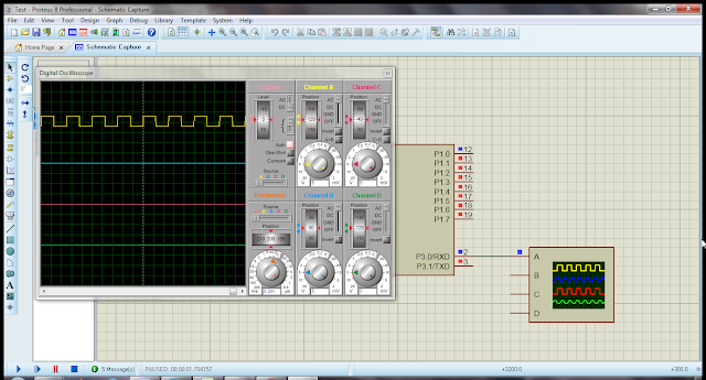
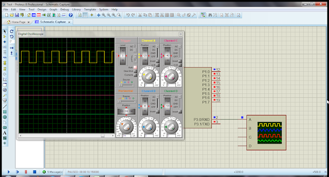
The following code demonstrate, how to blink LED using AT89C1051. The code is written in Keil uVision2 IDE and simulation is done with Proteus 8.0. At the end of code, you can find complete project files for download. Code Using Keil uVision2 #include // proto-types void Delayms(unsigned int x_time); // port pin labling sbit LED_0 = P1^0; void main(void) { // make pin as output LED_0 = 0; while(1) { LED_0 = ~LED_0; Delayms(500); } } void Delayms(unsigned int x_time) { unsigned int x,y; for(x=0;x<x_time;x++) for(y=0;y<122;y++); } Download Files For download Keil project and Proteus 8.0 simulation files,  click here .

GPIO as Output Programming of AT89C1051

Image
The following code demonstrate, how to make port-1 of AT89C1051 as output port for up-counter. The code is written in Keil uVision2 IDE and simulation is done with Proteus 8.0. At the end of code, you can find complete project files for download. Code Using Keil uVision2 #include // proto-types void Delayms(unsigned int x_time); // port-1 labling, 0x90 is the SFR address of port-1 sfr LED_PORT = 0x90; void main(void) { unsigned char count = 0x00; // make port as output LED_PORT = 0x00; while(1) { LED_PORT = count++; Delayms(200); } } void Delayms(unsigned int x_time) { unsigned int x,y; for(x=0;x<x_time;x++) for(y=0;y<122;y++); } Download Files For download Keil project and Proteus 8.0 simulation files,  click here .

Input Output Programming of AT89C1051

Image
The following code demonstrate, how to use AT89C1051 to control LED with ON/OFF switch. The code is written in Keil uVision2 IDE and simulation is done with Proteus 8.0. At the end of code, you can find complete project files for download. Code Using Keil uVision2 #include // proto-types void Delayms(unsigned int x_time); // port pin labling sbit LED_0 = P1^0; sbit SW = P3^2; void main(void) { LED_0 = 0; // as output SW = 1; // as input while(1) { LED_0 = ~SW; Delayms(10); } } void Delayms(unsigned int x_time) { unsigned int x,y; for(x=0;x<x_time;x++) for(y=0;y<122;y++); } Download Files For download Keil project and Proteus 8.0 simulation files,  click here .

How to Use RS232 Transmitter in AT89C1051 (Single Baud-Rate)

Image
The following code demonstrate, how to transmit serial data in AT89C1051. The code is written in Keil uVision2 IDE and simulation is done with Proteus 8.0. At the end of code, you can find complete project files for download. Code Using Keil uVision2 #include // proto-types void WriteData(unsigned char ch); void Delayms(unsigned int x_time); // port pin labling sbit LED_0 = P1^0; void main(void) { code char company_name[] = “eTechEd.com: Engineering and Technology Education!”; unsigned int index; LED_0 = 0; // as output SCON = 0x50; // SCON: mode 1, 8-bit UART, enable rcvr TMOD |= 0x20; // TMOD: timer-1, mode 2, 8-bit auto reload TH1 = -3; // reload value for 9600 baud //TH1 = -6; // reload value for 4800 baud //TH1 = -12; // reload value for 2400 baud //TH1 = -24; // reload value for 1200 baud TR1 = 1; // TR1: timer-1 run while(1) { for(index=0;index<sizeof(company_name);index++) { WriteData(company_name[index]); } WriteData(‘\r’); // carriage return ascii char LED_0 = ~

How to Use RS232 Transmitter in AT89C1051 (Double Baud-Rate)

Image
The following code demonstrate, how to transmit serial data in AT89C1051 with double baud-rate. The code is written in Keil uVision2 IDE and simulation is done with Proteus 8.0. At the end of code, you can find complete project files for download. Code Using Keil uVision2 #include // proto-types void WriteData(unsigned char ch); void Delayms(unsigned int x_time); // port pin labling sbit LED_0 = P1^0; void main(void) { code char company_name[] = “Engineering and Technology Education!”; code char baud_info[] = “Transmission with double baud-rate 9600 x 2 = 19200”; unsigned int index; LED_0 = 0; // as output PCON |= 0x80; // PCON: SMOD=1 for double baud rate SCON = 0x50; // SCON: mode 1, 8-bit UART, enable rcvr TMOD |= 0x20; // TMOD: timer-1, mode 2, 8-bit auto reload TH1 = -3; // reload value for 9600 baud //TH1 = -6; // reload value for 4800 baud //TH1 = -12; // reload value for 2400 baud //TH1 = -24; // reload value for 1200 baud TR1 = 1; // TR1: timer-1 run while(1) { for(

How to Use RS232 Receiver in AT89C1051 (Single Baud-Rate)

Image
The following code demonstrate, how to receive data from UART of AT89C1051. The code is written in Keil uVision2 IDE and simulation is done with Proteus 8.0. At the end of code, you can find complete project files for download. Code Using Keil uVision2 #include #include “stdio.h” // proto-types void WriteData(unsigned char ch); unsigned char ReadData(void); void Delayms(unsigned int x_time); // port pin labling sbit LED_0 = P1^0; void main(void) { code char company_name[] = “Engineering and Technology Education!\rWrite any Character in Transmitter Window:\r”; unsigned int index; char get_char; LED_0 = 0; // as output SCON = 0x50; // SCON: mode 1, 8-bit UART, enable rcvr TMOD |= 0x20; // TMOD: timer-1, mode 2, 8-bit auto reload TH1 = -3; // reload value for 9600 baud //TH1 = -6; // reload value for 4800 baud //TH1 = -12; // reload value for 2400 baud //TH1 = -24; // reload value for 1200 baud TR1 = 1; // TR1: timer-1 run for(index=0;index<sizeof(company_name);index++) { Wr

How to Use RS232 Receiver in AT89C1051 (Double Baud-Rate)

Image
The following code demonstrate, how to receive data from UART of AT89C1051 with double baud-rate. The code is written in Keil uVision2 IDE and simulation is done with Proteus 8.0. At the end of code, you can find complete project files for download. Code Using Keil uVision2 #include #include “stdio.h” // proto-types void WriteData(unsigned char ch); unsigned char ReadData(void); void Delayms(unsigned int x_time); // port pin labling sbit LED_0 = P1^0; void main(void) { code char company_name[] = “eTechEd.com: Engineering and Technology Education!\r”; code char baud_info[] = “Transmission with double baud-rate 9600 x 2 = 19200\rType in Transmitter Window->:”; unsigned int index; char get_char; LED_0 = 0; // as output PCON |= 0x80; // PCON: SMOD=1 for double baud rate SCON = 0x50; // SCON: mode 1, 8-bit UART, enable rcvr TMOD |= 0x20; // TMOD: timer-1, mode 2, 8-bit auto reload TH1 = -3; // reload value for 9600 baud //TH1 = -6; // reload value for 4800 baud //TH1 = -12; // r

How to Use RS232 Receiver in AT89C1051 Using Interrupt

Image
The following code demonstrate, how to receive data from UART of AT89C1051 on interrupt. The code is written in Keil uVision2 IDE and simulation is done with Proteus 8.0. At the end of code, you can find complete project files for download. Code Using Keil uVision2 #include #include “stdio.h” // proto-types void ConfigSerial(void); void ConfigInterrupt(void); void WriteData(unsigned char ch); unsigned char ReadData(void); void Delayms(unsigned int x_time); // port pin labling sbit LED_0 = P1^0; unsigned char rxd_buffer = 0; // interrupt service routine here static void com_isr (void) interrupt 4 { if(RI != 0) { RI = 0; rxd_buffer = SBUF; WriteData(rxd_buffer); } } void main(void) { code char company_name[] = “eTechEd.com: Engineering and Technology Education!\rType in Transmitter Window->:\r”; unsigned int index; LED_0 = 0; // as output // serial port configration ConfigSerial(); // interrupt setting ConfigInterrupt(); for(index=0;index<sizeof(company_name);index++) {

How to Use Counter-0 in AT89C1051 (16-bit Mode)

Image
The following code demonstrate, how to configure timer/counter 0 as a 16-bit counter. Each time port 3.4 goes low, the 16-bit counter is incremented by 1. The code is written in Keil uVision2 IDE and simulation is done with Proteus 8.0. At the end of code, you can find complete project files for download. Code Using Keil uVision2 #include <REG51.H> #include <stdio.h> // proto-types void ConfigTimer0AsCounter(void); void ConfigUART(void); void Delayms(unsigned int x_time); // port labling sfr COUNT_PORT = 0x90; sbit COUNT_0_IN = P3^4; void main(void) { // make port as output COUNT_PORT = 0x00; // make pin as input COUNT_0_IN = 1; // config counter ConfigTimer0AsCounter(); // config uart ConfigUART(); printf(“Counter-0 in 16-bit mode\n”); printf (“Press UP Count-0 button (T0 input)\n”); while(1) { if(COUNT_0_IN == 0) { COUNT_PORT = TL0; printf (“Counter-0 = %2.2bX%2.2bXh\n”, TH0, TL0); Delayms(300); } } } void ConfigTimer0AsCounter(void) { // set timer0 for 16-bit co

How to Use Counter-1 in AT89C1051 (16-bit Mode)

Image
The following code demonstrate, how to configure timer/counter 1 as a 16-bit counter. Each time port 3.5 goes low, the 16-bit counter is incremented by 1. The code is written in Keil uVision2 IDE and simulation is done with Proteus 8.0. At the end of code, you can find complete project files for download. Code Using Keil uVision2 #include #include // proto-types void ConfigTimer1AsCounter(void); void Delayms(unsigned int x_time); // port labling sfr COUNT_PORT = 0x90; sbit COUNT_1_IN = P3^5; void main(void) { // make port as output COUNT_PORT = 0x00; // make pin as input COUNT_1_IN = 1; // config counter ConfigTimer1AsCounter(); while(1) { if(COUNT_1_IN == 0) { COUNT_PORT = TL1; Delayms(300); } } } void ConfigTimer1AsCounter(void) { // set timer1 for 16-bit counter mode. // set C/T bit for counter TMOD = 0x50; // empty counter registers TH1 = 0x00; TL1 = 0x00; // start counter TR1 = 1; } void Delayms(unsigned int x_time) { unsigned int x,y; for(x=0;x<x_time;x++) for(y=0;y&l

How to Use External Interrupt-0 in AT89C1051

Image
The following code demonstrate, how to configure INT0 (external interrupt 0) to generate an interrupt on the falling-edge of INT0 (P3.2). Each time port 3.2 goes low, the port-1 is incremented by 1. The code is written in Keil uVision2 IDE and simulation is done with Proteus 8.0. At the end of code, you can find complete project files for download. Code Using Keil uVision2 #include #include // proto-types void ConfigExInterrupt0(void); void ConfigUART(void); void Delayms(unsigned int x_time); // port and pin labling sfr COUNT_PORT = 0x90; sbit LED = P3^0; // external interrupt-0 isr unsigned char ex0_isr_counter = 0; void ex0_isr(void) interrupt 0 { // Increment the count COUNT_PORT = ++ex0_isr_counter; } void main(void) { // make port as output COUNT_PORT = 0x00; // make pin as output LED = 0; // config interrupt-0 ConfigExInterrupt0(); while(1) { LED = ~LED; Delayms(300); } } void ConfigExInterrupt0(void) { // Configure interrupt 0 for falling edge on /INT0 (P3.2) IT0 = 1;

How to Use External Interrupt-1 in AT89C1051

Image
The following code demonstrate, how to configure INT1 (external interrupt 1) to generate an interrupt on the falling-edge of INT1 (P3.3). Each time port 3.3 goes low, the port-1 is incremented by 1. The code is written in Keil uVision2 IDE and simulation is done with Proteus 8.0. At the end of code, you can find complete project files for download. Code Using Keil uVision2 #include #include // proto-types void ConfigExInterrupt1(void); void ConfigUART(void); void Delayms(unsigned int x_time); // port and pin labling sfr COUNT_PORT = 0x90; sbit LED = P3^0; // external interrupt-1 isr unsigned char ex1_isr_counter = 0; void ex1_isr(void) interrupt 2 { // Increment the count COUNT_PORT = ++ex1_isr_counter; } void main(void) { // make port as output COUNT_PORT = 0x00; // make pin as output LED = 0; // config interrupt-1 ConfigExInterrupt1(); while(1) { LED = ~LED; Delayms(300); } } void ConfigExInterrupt1(void) { // Configure interrupt 1 for falling edge on /INT1 (P3.3) IT1 = 1;

How to Use Timer-0 Interrupt in AT89C1051

Image
The following code demonstrate, how to generate clock of 1.0Hz using timer-0 interrupt. Every 50,000 micro-second timer-0 interrupt is generated and the clock is generated on pin P3.0.  The code is written in Keil uVision2 IDE and simulation is done with Proteus 8.0. At the end of code, you can find complete project files for download. Code Using Keil uVision2 #include #include // proto-types void ConfigT0Interrupt(void); void Delayms(unsigned int x_time); // pin labling sbit PULSE = P3^0; sbit LED = P1^0; unsigned char timer0_isr_counter = 0; // timer-0 interrupt isr void timer0_isr(void) interrupt 1 { if(timer0_isr_counter++ >= 20) { PULSE = ~PULSE; // reload timer-0 registers TL0 = 0xB0; TH0 = 0x3C; } } void main(void) { // make pins as output PULSE = 0; LED = 0; // config timer-0 interrupt ConfigT0Interrupt(); while(1) { LED = ~LED; Delayms(500); } } void ConfigT0Interrupt(void) { // master clock is 12MHz // timer clock is 1/12th => 1MHz // in 16-bit mode timer overf

How to Use Timer-1 Interrupt in AT89C1051

Image
The following code demonstrate, how to generate clock of 10Khz using timer-1 interrupt. Every 50 micro-second timer-1 interrupt is generated and the clock is generated on pin P3.0.  The code is written in Keil uVision2 IDE and simulation is done with Proteus 8.0. At the end of code, you can find complete project files for download. Code Using Keil uVision2 #include #include // proto-types void ConfigT1Interrupt(void); void Delayms(unsigned int x_time); // pin labling sbit PULSE = P3^0; sbit LED = P1^0; // timer-1 interrupt isr void timer1_isr(void) interrupt 3 { // 10khz clock PULSE = ~PULSE; // reload timer-1 registers TL1 = 0xCE; TH1 = 0xFF; } void main(void) { // make pins as output PULSE = 0; LED = 0; // config timer-1 interrupt ConfigT1Interrupt(); while(1) { LED = ~LED; Delayms(500); } } void ConfigT1Interrupt(void) { // master clock is 12MHz // timer clock is 1/12th => 1MHz // in 16-bit mode timer overflow // after 65536 usec. // for overflow every 50 usec // 65,536-

How to Use Timer-0 in AT89C1051 (8-bit Auto-Reload Mode)

Image
The following code demonstrate, how to generate clock of 2.5Khz using timer-0 in auto reload mode. Every 200 micro-second timer-0 overflow flag goes high and  port P3.0 is inverted. The code is written in Keil uVision2 IDE and simulation is done with Proteus 8.0. At the end of code, you can find complete project files for download. Code Using Keil uVision2 #include #include // proto-types void ConfigTimer0(void); void MonitorTimer0OverflowFlag(void); void Delayms(unsigned int x_time); // pin labling sbit PULSE = P3^0; sbit LED = P1^0; void main(void) { // make pins as output PULSE = 0; LED = 0; // config timer-0 ConfigTimer0(); while(1) { PULSE = ~PULSE; MonitorTimer0OverflowFlag(); } } void ConfigTimer0(void) { // master clock is 12MHz // timer clock is 1/12th => 1MHz // in 8-bit mode timer overflow // after 256 usec. // for overflow every 200 usec // 256-200 = 6 (0x06) TH0 = 0x06; // set timer-0 mode-2 (8-bit auto-reload) TMOD = 0x02; // start timer-0 TR0 = 1; } void Moni

How to Use Timer-0 in AT89C1051 (13-bit Mode)

Image
The following code demonstrate, how to generate clock of 100Hz using timer-0 in 13-bit mode. Every 5000 micro-second timer-0 overflow flag goes high and  port P3.0 is inverted. The code is written in Keil uVision2 IDE and simulation is done with Proteus 8.0. At the end of code, you can find complete project files for download. Code Using Keil uVision2 #include #include // proto-types void ConfigTimer0(void); void MonitorTimer0OverflowFlag(void); void Delayms(unsigned int x_time); // pin labling sbit PULSE = P3^0; sbit LED = P1^0; void main(void) { // make pins as output PULSE = 0; LED = 0; // config timer-0 ConfigTimer0(); while(1) { PULSE = ~PULSE; MonitorTimer0OverflowFlag(); } } void ConfigTimer0(void) { // master clock is 12MHz // timer clock is 1/12th => 1MHz // in 13-bit mode timer overflow // after 8,191 usec. // for overflow every 5,000 usec // 8,191-5,000 = 3,191 (0x0C77) TL0 = 0x77; TH0 = 0x0C; // set timer-0 mode-0 (13-bit) TMOD = 0x00; // start timer-0 TR0 = 1;

How to Use Timer-0 in AT89C1051 (16-bit Mode)

Image
The following code demonstrate, how to generate clock of 1.0Hz using timer-0 in 16-bit mode. Every 50,000 micro-second timer-0 overflow flag goes high and  port P3.0 is inverted. The code is written in Keil uVision2 IDE and simulation is done with Proteus 8.0. At the end of code, you can find complete project files for download. Code Using Keil uVision2 #include #include // proto-types void ConfigTimer0(void); void MonitorTimer0OverflowFlag(void); void Delayms(unsigned int x_time); // pin labling sbit PULSE = P3^0; sbit LED = P1^0; void main(void) { // make pins as output PULSE = 0; LED = 0; // config timer-0 ConfigTimer0(); while(1) { PULSE = ~PULSE; MonitorTimer0OverflowFlag(); } } void ConfigTimer0(void) { // master clock is 12MHz // timer clock is 1/12th => 1MHz // in 16-bit mode timer overflow // after 65536 usec. // for overflow every 50,000 usec // 65,536-50,000 = 15,536 (0x3CB0) TL0 = 0xB0; TH0 = 0x3C; // set timer-0 mode-1 (16-bit) TMOD = 0x01; // start timer-0 TR0

How to Use Timer-1 in AT89C1051 (8-bit Auto-Reload Mode)

Image
The following code demonstrate, how to generate clock of 2.5Khz using timer-1 in auto reload mode. Every 200 micro-second timer-1 overflow flag goes high and  port P3.0 is inverted. The code is written in Keil uVision2 IDE and simulation is done with Proteus 8.0. At the end of code, you can find complete project files for download. Code Using Keil uVision2 #include #include // proto-types void ConfigTimer1(void); void MonitorTimer1OverflowFlag(void); void Delayms(unsigned int x_time); // pin labling sbit PULSE = P3^0; sbit LED = P1^0; void main(void) { // make pins as output PULSE = 0; LED = 0; // config timer-1 ConfigTimer1(); while(1) { PULSE = ~PULSE; MonitorTimer1OverflowFlag(); } } void ConfigTimer1(void) { // master clock is 12MHz // timer clock is 1/12th => 1MHz // in 8-bit mode timer overflow // after 256 usec. // for overflow every 200 usec // 256-200 = 6 (0x06) TH1 = 0x06; // set timer-1 mode-2 (8-bit auto-reload) TMOD = 0x20; // start timer-1 TR1 = 1; } void Moni

How to Use Timer-1 in AT89C1051 (13-bit Mode)

Image
The following code demonstrate, how to generate clock of 100Hz using timer-1 in 13-bit mode. Every 5000 micro-second timer-1 overflow flag goes high and  port P3.0 is inverted. The code is written in Keil uVision2 IDE and simulation is done with Proteus 8.0. At the end of code, you can find complete project files for download. Code Using Keil uVision2 #include #include // proto-types void ConfigTimer1(void); void MonitorTimer1OverflowFlag(void); void Delayms(unsigned int x_time); // pin labling sbit PULSE = P3^0; sbit LED = P1^0; void main(void) { // make pins as output PULSE = 0; LED = 0; // config timer-1 ConfigTimer1(); while(1) { PULSE = ~PULSE; MonitorTimer1OverflowFlag(); } } void ConfigTimer1(void) { // master clock is 12MHz // timer clock is 1/12th => 1MHz // in 13-bit mode timer overflow // after 8,191 usec. // for overflow every 5,000 usec // 8,191-5,000 = 3,191 (0x0C77) TL1 = 0x77; TH1 = 0x0C; // set timer-1 mode-0 (13-bit) TMOD =